Image shown is a representation only. Exact specifications should be obtained from the product data sheet.
Active

Texas Instruments
Texas Instruments Incorporated (TI) is a global semiconductor powerhouse, crafts advanced analog ICs and embedded processors. Fueled by top-tier minds, TI's innovations drive tech's future, impacting 100,000+ clients.


Bostock Quality Assurance


Product Details
Shipping
Reviews
HVD233HKX/EM 1 Features
Assured (RHA) MIL-PRF 38535 Qualified, SMD5962L1420901VXC– Single Event Latch-up (SEL) Immune to 86MeV-cm2/mg at 125°C– Total Ionizing Dose (TID) immune up 50 kRad(Si) at Low Dose Rate– Qualified over the Military Temperature Range(–55°C to 125°C)– High-Performance 8-Pin Ceramic Flat Pack(HKX) • Compatible With ISO 11898-2 • Bus Pins Fault Protection Exceeds ±16 V • Bus Pins ESD Protection Exceeds ±16 kV HBM • Data Rates up to 1 Mbps • Extended –7-V to 12-V Common Mode Range • High Input Impedance Allows for 120 Nodes • • Adjustable Driver Transition Times for ImprovedLVTTL I/Os are 5-V TolerantSignal Quality • Unpowered Node Does Not Disturb the BusLow Current Standby Mode, 200-μA Typical •Loopback for Diagnostic Functions • • Thermal Shutdown Protection • Power Up and Power Down With Glitch-Free BusInputs and Outputs– High Input Impedance With Low VCC– Monolithic Output During Power Cycling
HVD233HKX/EM 3 Description
The SN55HVD233-SP isspacecraftapplications employing the controller area network(CAN)inaccordance with the ISO 11898 standard. As a CANtransceiver, the device provides transmit and receivecapability between the differential CAN bus and aCAN controller, with signaling rates up to 1 Mbps.communication physicalseriallayerinV,overtemperatureDesigned for operation in especially harsh radiationenvironments, the SN55HVD233-SP features cross-wire, overvoltage, and loss of ground protection to±16shutdown)protection. This device operates over a wide –7-V to12-V common mode range. This transceiver is theinterface between the host CAN controller on themicroprocessor, FPGA, or ASIC, and the differentialCAN bus used in satellite applications.(thermalDevice Information(1)Simplified Schematic
HVD233HKX/EM 2 Applications
• Spacecraft Backplane Data Bus Communicationand Control • CAN Bus Standards Such As CANopen,DeviceNet, CAN Kingdom, ISO 11783, NMEA2000, SAE J1939used
HVD233HKX/EM 5 Description (continued)
Modes: The RS, pin 8 of the SN55HVD233-SP, provides for three modes of operation: high-speed, slope control,or low-power standby mode. The user selects the high-speed mode of operation by connecting pin 8 directly toground, allowing the driver output transistors to switch on and off as fast as possible with no limitation on the riseand fall slope. The user can adjust the rise and fall slope by connecting a resistor to ground at pin 8, because theslope is proportional to the pin's output current. Slope control is implemented with a resistor values of 0 Ω toachieve a single ended slew rate of approximately 38 V/μs up to a value of 50 kΩ to achieve approximately 4V/μs slew rate. For more information about slope control, refer to the Application and Implementation section.The SN55HVD233-SP enters a low-current standby (listen-only) mode during which the driver is switched off andthe receiver remains active if a high logic level is applied to pin 8. The local protocol controller reverses this low-current standby mode when it needs to transmit to the bus. For more information on the loopback mode, refer tothe Application Information section.Loopback: A logic high on the loopback LBK pin 5 of the SN55HVD233-SP places the bus output and bus inputin a high-impedance state. The remaining circuit remains active and available for driver-to-receiver loopback,self-diagnostic node functions without disturbing the bus.CAN bus states: The CAN bus has two states during powered operation of the device: dominant and recessive.A dominant bus state is when the bus is driven differentially, corresponding to a logic low on the D and R pin. Arecessive bus state is when the bus is biased to VCC / 2 through the high-resistance internal input resistors RIN ofthe receiver, corresponding to a logic high on the D and R pins (see Bus States (Physical Bit Representation)and Simplified Recessive Common Mode Bias and Receiver).
Product Attributes
| TYPE | DESCRIPTION | Select all |
|---|---|---|
| Package | Tube | |
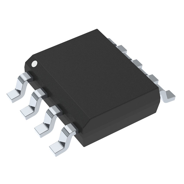
| Supplier Device Package | 8-CFlatpack | |
| Product Status | Active | |
| Type | Transceiver | |
| Protocol | CANbus | |
| Receiver Hysteresis | 100 mV | |
| Number of Drivers/Receivers | 1/1 | |
| Duplex | Half | |
| Data Rate | 1Mbps | |
| Supply Voltage | 3V ~ 3.6V | |
| Mounting Type | Surface Mount | |
| Package / Case | 8-CFlatpack |
Active
Texas Instruments
Texas Instruments Incorporated (TI) is a global semiconductor powerhouse, crafts advanced analog ICs and embedded processors. Fueled by top-tier minds, TI's innovations drive tech's future, impacting 100,000+ clients.
Bostock Quality Assurance
Popular Products
01 / 02
10
MC33567D-1R2
onsemi
IC LNR REG CTRLR 2OUT 8SOIC
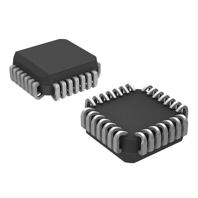
MC100E451FNG
onsemi
IC FF D-TYPE SNGL 6BIT 28PLCC
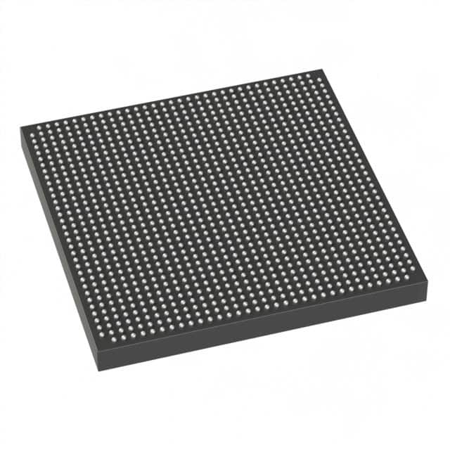
1SG065HH1F35E2VG
Intel
IC FPGA STRATIX10GX 1152FBGA
DS15MB200TSQ
Texas Instruments
IC MULTIPLEXER LVDS 4CH 48WQFN
RJK03P9DPA-00#J5A
Renesas Electronics America Inc.
POWER, N-CHANNEL MOSFET
CY2544QC013T
Infineon Technologies
IC CLOCK GENERATOR 24QFN
FS32K118LFT0VLHT
NXP USA Inc.
IC MCU 32BIT 256KB FLASH 64LQFP
LT1991ACDD#TRPBF
Analog Devices Inc.
IC OPAMP PGA 1 CIRCUIT 10DFN
MC74LCX646DWR2
onsemi
REGISTERED BUS TRANSCEIVER
AEAT-8800-Q24
Broadcom Limited
ROTARY ENCODER MAGNETIC 4096PPR